

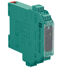
Relay Module KFD2-RSH-1.2E.L3-Y1
- 1-channel signal conditioner
- 24 V DC supply
- Logic input 20.5 V DC ... 26.4 V DC
- Recommended connectable voltage 50 V AC ... 230 V AC, 60 V DC ... 110 V DC
- Relay contact output for energized to safe function
- Line fault transparency (LFT)
- Diagnostic function
- Up to SIL 3 acc. to IEC/EN 61508


Please note: All product-related documents, such as certificates, declarations of conformity, etc., which were issued prior to the conversion under the name Pepperl+Fuchs GmbH or Pepperl+Fuchs AG, also apply to Pepperl+Fuchs SE.
Folhas de dados: Dados técnicos do KFD2-RSH-1.2E.L3-Y1
| General specifications | ||
|---|---|---|
| Signal type | Digital Output | |
| Functional safety related parameters | ||
| Safety Integrity Level (SIL) | SIL 3 | |
| Systematic capability (SC) | SC 3 | |
| Supply | ||
| Connection | Power Rail or terminals 14+, 15- | |
| Rated voltage | 19 ... 26.4 V DC | |
| Input current | max. 35 mA at 24 V DC , max. 44 mA at 19 V DC , with enabled internal fault detection | |
| Power consumption | < 1.7 W , includes the power consumption of the digital input , see derating curves | |
| Input | ||
| Connection side | control side | |
| Connection | terminals 7+, 8- | |
| Pulse/Pause ratio | min. 150 ms / min. 150 ms with disabled internal fault detection min. 1 s / min. 1 s with enabled internal fault detection |
|
| Test pulse length | max. 2 ms from DO card | |
| Signal level | 0-signal: -5 ... 5 V DC 1-signal: 20.5 ... 26.4 V DC |
|
| Rated current | 0-signal: typ. 1.6 mA at 1.5 V DC; typ. 8 mA at 3 V DC (maximum leakage current DO card) 1-signal: ≥ 36 mA (minimum load current DO card) |
|
| Inrush current | < 200 mA after 100 µs | |
| Output | ||
| Connection side | field side | |
| Connection | external voltage : terminals 5+/L, 2-/N load : terminals 6, 3 |
|
| Connectable voltage | 50 ... 230 V AC 60 ... 110 V DC |
|
| Power dissipation | < 3.3 W at 5 A , see derating curves | |
| Contact loading | 253 V AC/5 A/cos φ 0.7; 30 V DC/5 A resistive load , see derating curves | |
| Minimum switch current | 10 mA | |
| Mechanical life | 5 x 10⁶ switching cycles | |
| Line fault detection | low voltage < 35 V AC undercurrent: 10 mA AC; overcurrent: 5.5 A AC (relay energized) breakage: 48 kΩ; short-circuit: 29 Ω (load, relay de-energized) |
|
| Fault indication output | ||
| Connection | terminals 10, 11 | |
| Contact loading | 30 V DC/ 0.5 A resistive load | |
| Reaction time | < 2 s | |
| Mechanical life | 105 switching cycles | |
| Transfer characteristics | ||
| Switching frequency | < 3 Hz with disabled internal fault detection < 0.5 Hz with enabled internal fault detection |
|
| Galvanic isolation | ||
| Input/power supply | basic insulation according to IEC/EN 61010-1, rated insulation voltage 60 Veff | |
| Input/fault indication output | basic insulation according to IEC/EN 61010-1, rated insulation voltage 30 Veff | |
| Output/other circuits | reinforced insulation according to IEC/EN 61010-1, rated insulation voltage 300 Veff | |
| Indicators/settings | ||
| Display elements | LEDs | |
| Control elements | DIP switch | |
| Configuration | via DIP switches | |
| Labeling | space for labeling at the front | |
| Directive conformity | ||
| Electromagnetic compatibility | ||
| Directive 2014/30/EU | EN 61326-1:2013 (industrial locations) | |
| Low voltage | ||
| Directive 2014/35/EU | EN 61010-1:2010 | |
| Conformity | ||
| Electromagnetic compatibility | NE 21:2017 , IEC/EN 61326-3-2:2018 , EN 61326-3-1:2017 | |
| Degree of protection | IEC 60529:2013 | |
| Ambient conditions | ||
| Ambient temperature | -20 ... 60 °C (-4 ... 140 °F) Observe the temperature range limited by derating, see section derating. |
|
| Mechanical specifications | ||
| Degree of protection | IP20 | |
| Connection | screw terminals | |
| Mass | approx. 134 g | |
| Dimensions | 20 x 119 x 115 mm (0.8 x 4.7 x 4.5 inch) (W x H x D) , housing type B2 | |
| Height | 119 mm | |
| Width | 20 mm | |
| Depth | 115 mm | |
| Mounting | on 35 mm DIN mounting rail acc. to EN 60715:2001 | |
| General information | ||
| Supplementary information | Observe the certificates, declarations of conformity, instruction manuals, and manuals where applicable. For information see www.pepperl-fuchs.com. | |
Classifications
| System | Classcode |
|---|---|
| ECLASS 13.0 | 27210101 |
| ECLASS 12.0 | 27210101 |
| ECLASS 11.0 | 27210101 |
| ECLASS 10.0.1 | 27210101 |
| ECLASS 9.0 | 27210101 |
| ECLASS 8.0 | 27210101 |
| ECLASS 5.1 | 27210121 |
| ETIM 9.0 | EC001485 |
| ETIM 8.0 | EC001485 |
| ETIM 7.0 | EC001485 |
| ETIM 6.0 | EC001485 |
| ETIM 5.0 | EC001485 |
| UNSPSC 12.1 | 39121543 |
Details: KFD2-RSH-1.2E.L3-Y1
Datasheet: KFD2-RSH-1.2E.L3-Y1
| Datasheet | Tipo de Arquivo | Tamanho do Arquivo |
|---|---|---|
| Datasheet KFD2-RSH-1.2E.L3-Y1 | 1093 KB | |
| Fiche de données KFD2-RSH-1.2E.L3-Y1 | 1173 KB | |
| Datenblatt KFD2-RSH-1.2E.L3-Y1 | 1093 KB | |
| Datasheet KFD2-RSH-1.2E.L3-Y1 | 1246 KB | |
| Hoja de datos KFD2-RSH-1.2E.L3-Y1 | 1177 KB |
Documents: KFD2-RSH-1.2E.L3-Y1
CAD+CAE: KFD2-RSH-1.2E.L3-Y1
| CAD | Tipo de Arquivo | Tamanho do Arquivo |
|---|---|---|
| CAD 3-D / CAD 3-D | STP | 2510 KB |
| CAD Portal / CAD Portal | LINK | --- |
Approvals+Certificates: KFD2-RSH-1.2E.L3-Y1
| Certificates | Tipo de Arquivo | Tamanho do Arquivo |
|---|---|---|
| Worldwide TUV Rheinland Functional Safety Certificate | 650 KB | |
| cULus | 266 KB | |
| Declaration of Conformity | ||
| EU Declaration of Conformity (P+F) / EU-Konformitäterklärung (P+F) | 71 KB |
Produtos Relacionados: KFD2-RSH-1.2E.L3-Y1
| Matching System Components | ||||||
|---|---|---|---|---|---|---|
|
||||||
|
||||||
|
||||||
|
||||||
|
||||||
|
||||||
| Accessories | ||||||
|
||||||
|
||||||


Choose from various selection criteria like safety integrity level, performance level, device function, and signal type and find the SIL/PL assessed device that you are looking for.
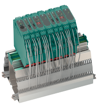
A Pepperl+Fuchs está estabelecendo um novo nível de confiabilidade com relés de segurança recém-desenvolvidos. Com contatos de comutação multirredundantes, o módulo de interface do Sistema-K comprovado e testado fornece ativação e desativação confiáveis e relacionadas à segurança para aplicações de acordo com o padrão IEC61508 até SIL 3.


Pepperl+Fuchs Ltda.
Rua José Versolato, 111
Domo Corporate Tower, Conjunto 144
09750-730 São Bernardo do Campo, SP
Brasil
vendas@br.pepperl-fuchs.com
 +55 11 4007 1448
A Pepperl+Fuchs é líder na fabricação e no desenvolvimento de sensores e componentes eletrônicos para o setor global da automação industrial. Inovação contínua, qualidade e crescimento constante garantem o nosso sucesso há mais de 70 anos. Empregamos mais de 6.300 colaboradores em todo o mundo e contamos com fábricas próprias na Alemanha, Estados Unidos, Cingapura, Hungria, Indonésia e Vietnã, todas com certificação ISO 9001.